VPT 3D-Viewer TutorialUsing WinFrame3D |
. 
|
1. Prepare Geometry Data
The VPT-WinFrame3D-Viewer, hereafter called WF3d, can be run interchangeably from a stored file or from a live socket. Sometimes it is handy to combine a mixture of both methods. For example, define the landscapes, fixed structures, and vehicle shapes in a file which rarely changes. Then control the movements of vehicles via sockets from your simulation models. The command formats are the same either way. Therefore we will not dwell on the specific interface at this point.In the drawing and managing graphical objects, the basic steps are as follows:
- Specify Initial Camera Settings - The camera setup must be set first before anything else. You specify the initial location of the camera, it's pointing direction, and lens settings, such as view-angle and depth-of-field. This is simple and straight forward. See: Setting camera position, field of view, and aiming.
- Define the object types - This defines the shape, size, color, and texture of the classes of objects you will display and manipulate. However, this does not populate, instantiate, or place the object anywhere in the viewable space. For example, we might define the shape, color, and size of a vehicle such as a Hum-V. As a type definition, this does not specify how many instances of the Hum-V objects there will be, or where they will be, if any. Each object-type defined is given a Type-Name. There are many ways to define objects. See: Defining Object Types.
- Instantiate Objects - By instantiating objects, you populate the viewable space with the pre-defined object types. You specify an Instance-Name, it's Type, as well as the location and orientation (position) of each object instance, and in this way, the total number of instances. For example, you may place one or even a thousand of the Hum-V objects. This is fairly simple and straight forward. See: Instantiating Objects..
- Move Some of Your Objects - Specify the motion of objects by Instance-Name and their movement between point P1 at time T1, and point P2 by time T2. And/or specify their rotation about their own axis in degrees from time T1 to T2. And/or specify circular orbits or curvi-linear motion about arbitrary points of rotation, radius, and times. The movement commands can be sent while the viewer is running, but remember the viewer runs in real-time. The times (T1,T2) are relative to the viewer's real-time clock. Make sure movement commands are sent prior to, -or at same time as-, the movement time (preferably T1). Commands sent with T2 less than the present time will be ignored. You can place many objects in motion simultaneously this way. Newer commands, which overlap the time of older commands, take precedent so that simulation events are registered as they arrive. Example, you can put vehicles in certain motions until otherwise updated. See: Moving Objects. [Recently, time-relative versions of all move commands have been added. This allows you to specify movements in real-time, regardless of the synchronization between the simulator and the viewer. For example, mo_rel instructs the viewer to move the object for a duration beginning when received.]
1.1 Adding fprintf's or Socket Calls to Models
Add fprintf or socket calls to your models to generate the above commands.. . .
You can specify geometries and commands in any combination of files and sockets. Useful ideas include making separate files for various kinds of object definitions such as:
- mountains_low.dat, mountains_high.dat, lakeP.dat, city1.dat, city2.dat landscapeA.dat.
- TankA1A.dat, F18.dat, E2C.dat, Hum-V.dat, etc.
While all the above might be defined in static files which can be mixed and matched for rapid configuration, the movement commands may be provided by live simulation programs through sockets.
Example:
wf3d camera.dat highland_range8.dat city32.dat DesertMissionA.dat -soc 32455 -soc 33333
In this example, basic definitions of objects are provided by various combinations of files. Instantiations are provided by other files, and the movement of entities are controlled by a combination of simulators, perhaps controlling the foe and friendly forces diametrically opposed. - Or, everything could be combined into a single file, such as for archival playback.
1.2 Choosing Coordinate Region for Your Virtual World
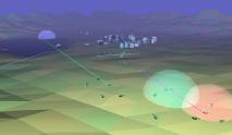
You will specify the locations of your objects in Cartesian 3-space (x, y, and z). The values may be anything you want, to place objects where they are needed. There are no minimums or maximums as far as the WF-3D tool is concerned. However, there is a min and max range that you set in the camera statement, which defines the viewable frustum in the initial camera position. Naturally you can move the camera position, but the "depth of field" remains the same.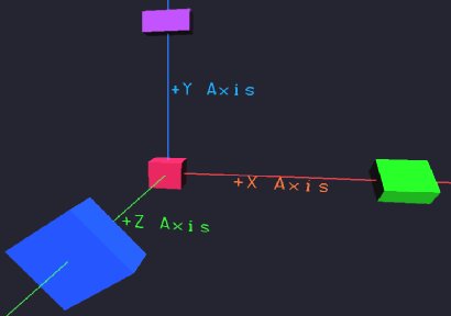 |
Figure 1 - WinFrame Coordinate Aves.
Once you have decided on the region of your virtual world, set the camera position to be either somewhere
within the region, or slightly back from it, to one side, at slight altitude aiming toward the center.
Example: Initial camera position x=0.0, y=800, z=-6000
Initial camera point-at x=0.0, y=0.0, z=0.0
And then you can populate objects within the -5km x 5km space in X-Z,
and at altitudes in Y from 0.0 to a few thousand meters.
You can always move the camera once the viewing starts. Above is just an example, you can always define a different game/map region which could be oblong, etc..
2. Run Simulation with 3D-Viewer
Invoke WF3D with the file(s) and/or socket(s) which will drive the animation, as shown in the example above. If you invoke WF3D without any files on the command-line, it will prompt you for a file to load by opening a file-browser. You can then navigate to, and select the file you want to display.When WF3d displays a scene, you will see a Controls button on the upper left of the screen. Pressing it will open a small control panel, which contains a small set of commonly used controls, as shown below.
A similar, but richer set of controls is also listed after the version number on the text window from which you started WF3d, or by pressing the Help button on the control-panel, as shown below:
 1. Move camera into scene (zoom-z).
 2. Move camera around scene (xy).
 3. Translate camera over scene (xy+aim).
 4. Rotate camera about scene (xz).
 5. Move camera's aim-point. (xz).
 6. Move camera's aim-height. (y).
 7. Zoom camera to/from origin (xyz).
 8. Move last-added object (xz).
 9. Rotate last-added object (y-axis).
 s. Stop/start AutoPan - Automatic camera rotation about origin.
 t. Start/stop AutoTour of outer loop..
 v. Value for speed setting, stops, prompts & accepts value.
 z. Start/stop AutoZoom - Automatic zoom toward origin.
 p. Snap Picture.
 c. Show Camera Coordinates.
 m. Meta functions.
 h. Help.
 q. Quit.
        Meta Functions:
         1. View Angle (FOV)
         2. Near-Field Limit
         3. Far-Field Limit
         m. Toggle back to non-meta mode.
Clicking the function in the control panel, or pressing the number or letter shown in the menu (with mouse focus in the WF3d window),
either puts the viewer in the mode to control the specified attribute or carries out the intended function.
The mouse scroll-wheel zooms in and out.
For example, pressing 1 causes left-right arrow presses (or mouse left-right movements) to move the camera position along the Z-axis toward or away from the origin. Pressing 2 causes the arrow keys (or mouse) to move the camera in the X-Y plane. With a little practice, you can become adroit at manipulating the camera's position and pointing direction, around and through a scene.
Other commands, such as p cause a picture to be snapped of the current scene, without altering the pointing mode. Pressing c causes the camera's coordinates to be displayed. This is handy when trying to find a good initial camera setting to place in a file.
The letters s, t, and z put the camera into pre-planned trajectories of continuous motion. S Scans around a circular orbit of the origin at whatever radius you position it. You can even change the radius as it scans. T takes the camera on a Tour which follows a similar orbit, but looks ahead in the direction of motion, instead of toward the center. Z Zooms the camera toward the origin, where it begins a slow rotation looking out around the horizon. Pressing any of these letters a second time, stops the camera's motion. Pressing it again resumes it. You can switch smoothly between motions by simply switching between them directly.
Less frequently used commands are relegated to the second level Meta menu. Go into / or out-of the meta mode by pressing m.
Some other arcane commands are not listed, such as:
- f - Freeze/unfreeze the movement of all entities (not including the camera).
- i - Identify-Object by Mouse Click. See below.
- - - Reverse camera panning direction.
- ~ - Slow camera panning speed.
- + - Increase camera pan speed.
- r - Adjust the viewing Rate. In this mode, use arrow keys to dilate or compress time (slow-down or speed-up the animation), while the viewer is running. Dilation or compression amount is displayed. See also -speed xx command-line option, for setting speed at invocation time.
.
Command-Line Options-
Several useful run-time command-line options are available. For a summary of the available options, see: WF3d Command Line Options.
WF-3D Operating Instructions -
The above tutorial describes one typical usage method. The WF-3D Operating Manual is a reference document describing how to operate WF-3D in general, together with a description of all operating commands. See: WF-3D Viewer Operation..
See also: WF3d