and the SCHEDULER Utility |
|
Contents:
- Introduction
- Graph Syntax
- Node Attributes
- Arc Attributes
- Macros and Graph-Variables
- Usage
- Rate Monotonic Scheduling
- Outputs
- Command-Line Arguments
- Appendix A - File Format
- Appendix B - STIM-Scheduler Variant
- Appendix C - Dynamic Scheduler
- Appendix D - Special Attribute Options
- Appendix E - Mapping Hints
- Appendix F - DFG Animation
Introduction:
A Data-Flow-Graph (DFG) describes the tasks and inherent data-dependencies of applications or processes; Examples include: manufactoring processes, job-scheduling, and parallel software applications. The SCHEDULER utility accepts DFG files and after partitioning, allocating, and scheduling the flow-graph nodes, produces corresponding job-sequences for each resource. In computer systems, these can be used as software-programs for each of the targeted processor elements (PEs).The SCHEDULER tool can perform the partitioning/mapping/scheduling operation automatically, or you can assist by specifying (all or some of) the mappings and the tool will do the tedious work of generating the individual job-sequences (or PE-programs) and calculating the indices to move job-tokens (or for sending+receiving data items), etc..
As initially configured, the SCHEDULER utility produces time-line plots and pseudo-code that is directly interpretable by CSIM PE models. Once a satisfactory mapping has been determined, the pseudo-code can be conveniently expanded to compilable C-source code for specific processor families.
The input to the SCHEDULER is an XML DFG text file, which is often drawn with CSIM's GUI. The format of the DFG input file is published in Appendix-A that is generated by CSIM's GUI, or other tools.
Graph Syntax:
A DFG consists of nodes and arcs. The nodes represent computational tasks, while the arcs represent data dependencies, buffering, and the direction of data transfer between task-nodes. A task-node cannot execute until sufficient data exists on its input arcs. When the data-amount threshold has been reached on each of its input arcs, a node can fire. When a node fires, it consumes data from its input arcs, executes the task, and it produces data onto its output arcs. Therefore, each arc is characterized by its produce, threshold, and consume amounts. Figure 1 shows an example of a very simple DFG.
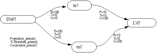
Figure 1 - Example of a simple Data Flow Graph (DFG).
This graph syntax, and this over-all method for developing parallel algorithm software and systems, is based on well developed and documented principles formally called computational flow graphs that are closely related to Petri net theory. See [1] for the formal background.
DFGs can be hierarchical. A hierarchical DFG contains nodes that are subgraphs. The subgraphs are drawn on separate diagrams. The top-level graph must have one START node, and one EXIT node.
Nodes with instance names beginning as GEN are special in that they produce periodic data at a specific interval; also called a monotonic interval. You may have multiple GEN nodes in a DFG, but each name must be unique. Any node in which the first three letters are GEN will be considered a GEN node. For instance, GEN1, GENa, GEN2, etc. are all GEN nodes.
Because the START, GEN, and EXIT nodes are often considered special control nodes, they are often not mapped to any physical processor element. You can do this by specifying their type as NO_PE. Actually, any node can be set as a NO_PE type node. Such nodes do not have to wait for any PEs to become available, and their input and output arcs do not imply nor generate data-transfers, since their existence is only logical (conceptual) there is no place to transfer data to-or-from. However, their effect relative to the DFG is taken into account as far as triggering their dependent nodes accordingly.
Node Attributes:
Nodes are characterized by five attributes:- Instance Name
- Type
- Compute Time
- Iterations
- Mapping Assignment (optional)
Three special type options provide additional control as to how a task is mapped to processor elements. These options are:
- NO_PE - Do not map task to a physical processor. This task's firing will depend only on input arc amounts. It will not wait for an available processor, nor will it execute or consume time on any processor. This option is intended as a convenience to assist in flow control.
- GetAny - Map to any-of or first-available processor in the mapping list. This option applies when more than one processor is named in the mapping assignment. The default mapping mode assigns the processors strictly by the order they occur in the mapping assignment list. Although the default appropriately describes many systems, it may not apply to systems which can dynamically select the next available processor from a group. This option applies to the latter case, and avoids waiting for one processor, when others are available.
- RunOnPrevious - Forces task to run on the same processor as the previous task did. This option is intended for pipeline operations with a single stream of execution. For tasks having multiple inputs, the mapping behavior of this option is undefined.
- Multicast node - set the node type to Mulicast. Arcs emanating from this node are handled as a multicast message. The scheduler generates a *.prog file with a 'pendmessg' instruction for each arc followed by a 'multimessg' instruction. The ProduceSequence attribute may be used with arcs associated with the multicast node to force an ordering of how messages are sent.
- SINK node - set the node type to SINK. This forces the scheduler not to generate 'recvmessg' or 'compute' instructions for the node.
- LITERAL_OP node - set the node name to begin with the string "LITERAL_OP". The node type is passed to the *.prog file and executed by the processor. This feature allows the scheduler to pass special user defined operations in the node type field such as 'check_exec' used in the multi_priority_pe.
By convention, the Compute Time is often specified in micro-seconds (uSec). It indicates how long a processor is busy computing the task. It also determines the time between when the output data is produced onto the node's output arcs from when the task began to execute. Time is a floating- point quantity.
Some tasks do not produce their output data in one batch at the completion of a firing. Rather, they produce data in several batches during their execution. To describe this behavior, and many others as well, nodes have an iteration parameter. The Iterations parameter determines how many times a node will execute and produce data for one firing. Here a firing means the satisfaction of the node's input thresholds and consumption of one batch of input data. Normally, the iteration parameter is one (1). The iteration value is an integer. The time between successive output iterations is the compute time of the node.
For example, if a task executes for 100-mS and produces 10 batches of data in this time at equally spaced intervals, then the task would be described as a DFG node having 10-iterations, and a compute-time of 10-mS. Once a node fires, it is assigned to a specific processor element and all iterations of the task occur on that processor.
The final optional parameter of a DFG node is the Mapping Assignment. This is an optional parameter. The mapping parameter designates the specific processor element a task will execute on. A list of processor assignments can be specified. A list is equivalent to specifying that each instance of the task is to execute on the respective sequence of processor elements. For example, the first instance of the task is to execute on the first listed processor, the second on the second, etc.. If the list is exhausted, the next instance is assigned to the first processor on the list in a round-robin fashion.
Additional Optional Node Attributes:
Aside from the traditional required parameters described above, an additional optional attribute is available:- Replicate - The Replicate parameter is used to simplify graphs having N identical parallel branches. It allows you to express parallelization with a parameter which can be conveniently changed without modifying the structure of the graph. With the Replicate attribute, a given set of parallel nodes can be drawn (collapsed) as a single node, with a single set of input and output arcs. The number of parallel copies of the node is set via the node's Replicate attribute. The Scheduler then automatically replicates the necessary input and output arcs, and manages the parallel branches of the node. See Parametric DFG Mapping for a more detailed discussion with examples.
Arc Attributes:
An arc is a directional connection between two nodes. It represents a dependency or flow of data between tasks. The end of the arc connected to the task-node which supplies the data is called the source. The end to which data flows is called the destination. The nodes connected by an arc are referred to as the source and destination nodes of the arc, respectively.An arc implies a potential buffer, queue, or temporary storage of data between task-operations. We speak of the amount of data held by an arc as the data in the arc's associated buffer. An arc is characterized by its produce, threshold, and consume amounts. These are parameters that influence how a graph executes. The amount of data held by the arc's buffer varies dynamically as the graph executes.
Arcs are characterized by 5 attributes.
- Threshold Amount,
- Consume Amount,
- Produce Amount,
- Initial Amount, and
- Source and Destination Names
An arc's initial-amount is normally zero. This suffices for feed-through DFG graphs, but causes graphs containing feed-back to dead-lock because the node receiving a feed-back-arc can never fire the first time. The initial-amount can be set to a non-zero integer quantity. This is sometimes called, priming-the-pump. Non-zero initial-amounts are rarely be used. Most users can ignore it because it automatically defaults to zero. However, it is available when needed.
There can be several arcs connected to a given node. To distinguish the data carried by each arc coming into -and going out of- a node, a name can be given to the destination and source of each arc, respectively. The source and destination names are not relevant on a flat graph for performance modeling because no data actually flows. However they become relevant for functional flow-graph modeling, target code-generation, and for connection of internal-to-external arcs on any kind of hierarchical graphs. For target code-generation, the source and destination names become the subroutine parameter names used in the generated code.
Additional Optional Arc Attributes:
Aside from the traditional required parameters described above, some additional optional attributes are available, as follows:- ProduceSequence - Normally, the Scheduler sequences the sending
of output arc data somewhat arbitrarily. Although it attempts to schedule
transfers by the order they are needed, the intelligent designer may wish
to alter the transfer sequence in some circumstances. By setting the
ProduceSequence attribute on designated arcs, you can fine-tune the
overall execution of your graphs. The ProduceSequence is used to
specify the order that the SEND instructions will be generated for
the output arcs of a given DFG-node. Example: 1, 2, 3, ...
By default, all arcs have ProduceSequence = 1, and are essentially tie.
Arcs with higher sequence numbers will be sent after arcs with lower sequence numbers.
Example:
ProduceSequence = 4 - XferType -
To specify a data-pull or Read operations on networks such as Raceway, add the
xfertype = pull attribute to the DFG arc for that transfer.
Example: (Arc attribute)
xfertype = pullThis setting causes the Scheduler to generate postmessg / readmessg command-pairs in the .prog files instead of the normal sendmessg/recvmessg pairs, respectively. The readmessg will be sequenced after any recvmessg(s) prior to a given compute task.
- NoXfer -
Sometimes an arc is used to force a dependency without meaning to imply a data
transfer (SEND/RECEIVE). Setting an acr's NoXfer attribute to True will
prevent Scheduler from generating SEND/RECEIVE instructions for the arc, suppressing
the transfer.
- SilentXfer -
To use an arc to force dependency in both the scheduler and in
the hardware device models without using a physical network link, or to portray
data transfer through an "ether" as in wireless models, set the arc's SilentXfer
attribute to True. The Scheduler will generate produce/consume instructions in
the .prog files instead of the normal sendmessg/recvmessg instructions,
respectively.
- Waypoints - To specify waypoints for routing the message data on the physical
hardware network, click Routing Explicit Waypoint Paths
Macros and Graph-Variables:
You can define frequently referenced values, expressions, or changeable parameters as macros that are defined in a common place Macros can be defined and modified under the EDIT / MACRO menu of the GUI editor. To define a macro, use the macro name you wish to define, followed by an equals sign, and then the value or expression you wish to define it as. Macro definitions can contain other macros and will be evaluated accordingly. Expressions can contain parenthesis, addition, subtraction, multiplication, and division on integers or reals. Macros can also be character strings. For example:
	mSec = * 1.0e3
	Sec = * 1.0e6
	Minutes = * 60.0 Sec
	FFT_Delay = 0.68 mSec
	FFT_Size = 4096
	FIR_Node = FFT_Delay
	MATMUL = FFT_DELAY * 40.7 + 2.3
	PE2  = Board1Mcm0Pe0
These macros can then be used anywhere in the DFG. Their values will be replaced prior to evaluating the DFG. Arbitrary arithmetic expressions will be evaluated for macros.
Several basic functions are available for use within expressions.
- RANDOM - Evaluates to a random floating-point value between 0.0 and 1.0.
- SQRT(x) - Returns the square-root of the argument. A floating-point value.
- LOG(x) - Returns the natural logarithm of the argument. A floating-point value.
- LOG10(x) - Returns the logarithm (base-10) of the argument. A floating-point value.
- EXP(x) - Returns the exponential ex of the argument. A floating-point value.
- EXP10(x) - Returns the exponential 10x of the argument..
- ABS(x) - Returns the absolute value of the argument. Preserves type: integer or float.
- TRUNC(x) - Truncates a floating-point value to integer without rounding. Returns integer.
- ROUND(x) - Rounds a floating-point value to integer. Returns integer.
- FLOAT(x) - Converts integer to float-type. Returns type float.
- SQR(x) - Returns the square of the the argument. Preserves type: integer or float.
- MIN(x,y) - Returns the lessor of x or y.
- MAX(x,y) - Returns the greater of x or y.
- SIN(x) - Returns the sine of x (where x is in radians).
- COS(x) - Returns the cosine of x (where x is in radians).
- POW(x,y) - Returns the power of x raised to the y.
Note that macros are not data-variables in the normal sense of variables in program code. Although in many respects they are similar, except that the macros are expanded and evaluated in each instance. (Deferred evaluation.)
For example:
	macro a = 5
	macro b = 2 * a
					print a, b
						a = 5,
						b = 2*a = 10

	macro a = 7
					print a, b
						a = 7,
						b = 2*a = 14
This could result in infinite recursion for self-inclusive macros.
A related class, called variable, assigns the current evaluated value to the object name. (Immediate evaluation.)
For example:
        macro a = 5
        variable b = 2 * a
					print a, b
						a = 5,
						b = 10

        macro a = 7
					print a, b
						a = 7,
						b = 10
The variable type is especially valuable when using random numbers.
For example, often several values depend on one random quantity.
This would not be possible to express with macros, because each reference
would be a new call to the random generator. Instead, one random number
can be generated and saved as a variable and the same value can be referenced
multiple times.
For example:
Using a variable to store the RANDOM value:

	variable message_size = ROUND( 1000 * RANDOM )
	macro Bandwidth = 100.0
	macro xfer_delay = message_size / Bandwidth

					print message_size, xfer_delay
						message_size = 375
						xfer_delay = 3.75

					print message_size, xfer_delay
						message_size = 375
						xfer_delay = 3.75

But with only macros:

	macro message_size = ROUND( 1000 * RANDOM )
	macro Bandwidth = 100.0
	macro xfer_delay = message_size / Bandwidth

					print message_size, xfer_delay
						message_size = 375
						xfer_delay = 5.21

					print message_size, xfer_delay
						message_size = 863
						xfer_delay = 1.09

       (RANDOM was re-evaluated on each reference of the macro.)
Usage:
The SCHEDULER utility expects the DFG source file to be the first command-line argument. If no arguments are specified, it will prompt you.The SCHEDULER accepts, as the optional second command-line argument, the netinfo file produced by the net_extract command of the CSIM simulator. This ensures consistency with the name- to -logical-ID numbers used by the ROUTER and the simulation models themselves.
     Example:
                scheduler  radar.dfg   netinfo
If no netinfo file is on the command-line, then the SCHEDULER knows nothing
about the architecture it is mapping to, nor what processors are available.
In this situation, the SCHEDULER will ask for the number of processors the DFG should
be mapped to.
In either case, the SCHEDULER will then perform the mapping by either using the user-supplied assignments or a set of heuristics that attempt to balance the processing load equally among processors, to minimize the processing latency, and to minimize inter-PE communications traffic by making maximum use of high data locality (I.E. automatic mapping).
In general, the automatic mode is less optimal than manually optimized mappings. However, the automatic mode is useful for quick first-cut attempts and it will be improved over time.
During scheduling, you will see the list of assignments being made as the DFG(s) executes.
Rate Monotonic Scheduling (RMS):
To use Rate Monotonic Scheduling (RMS) with the CSIM Scheduler, the -stim scheduler option is to be used with properly prepared DFG files. The files may be generated automatically with the dfg_gen utility from *.txt files generated by spread-sheets. Or, it may be generated manually with the CSIM DFG GUI. The scheduler generates *.prog files that are intended to be used with the multi_priority_pe.
Each task block that runs at an independent monotonic rate is to be graphed as a separate data flow graph. A 'stim_file' lists all the graphs to be used.
Each graph that represents a separate task block must have START and EXIT
nodes specified. If the graph is to be scheduled at a monotonic rate, a graph
attribute or macro is to define it as RMS = 1 or true. The rate at which
the graph is to be repeated is defined by a GEN node which follows the START
node. The loop may be terminated by either a time limit or a loop count.
The graph attributes:
looptime = "time limit"
or
loopcount = "number"
may be used.
The scheduler generates the *.prog files. If a looping attribute is used, the task blocks are unwrapped in the *.prog files until the looptime or loopcount is reached. Unique message ID's are used for each iteration.
If no loop attribute is used, the graph is executed only once.
To schedule the files for RMS scheduling, invoke:
sched -stim stim_file netinfo
Note the format of the *.prog files generated. Each task begins with TASK and ends with END_OF_TASK. The first statement after TASK is a monotonic statement which specifies the loop time. The last statement in each *.prog file is a 'progmdone' line.
Global Attributes for RMS:
- macro RMS = 1
Defines the graph to used for rate monotonic scheduling - macro looptime = 100.000000
Defines the time limit for repeating the graph in RMS mode.
(100.0 microseconds in this example) - macro loopcount = 10
Defines the number of times to repeat the graph in RMS mode. (10 times in this example)
Outputs:
The SCHEDULER produces three (3) types of output files:- pe_xx.prog - Pseudo-code program files: One for each processor element. (See pseudo-code instruction set for format information.)
- IdealTline.dat - Ideal time-line plot-file of task executions.
- IdealSpiderweb.dat - Ideal time-line plot of communication dependencies, often called a spiderweb-plot due to its appearance.
The time-line plots are considered ideal because the static SCHEDULER bases its estimates of task completion and communication times on a simplistic ideal model. The ideal time-lines are useful to compare with the actual time-lines produced by detailed architecture simulations. The comparison highlights the effects of architectural issues on the given mapping.
The ideal time-line can be viewed with XGRAPH
by selecting Tools / Plot Ideal Timeline from the GUI menu.
Or by typing:
xgraph IdealTline.datThe resulting graph shows the projected activities of the processors versus time.
It is usually helpful to overlay the inter-processor communication dependencies underneath the activity time-line. This produces a very complete picture of the data-flow-graph's execution history. You can do this by placing both plot-files on the XGRAPH command-line, as in:
xgraph IdealSpiderweb.dat IdealTline.dat(Placing the activity time-line second, ensures that the horizontal activity-bars are drawn over-top the diagonal communication traces. This gives the activity-bars priority which prevents their obscuration.)
Each horizontal processor activity bar-segment on the time-line plot corresponds to the execution of a DFG-node-task on the given processor. The SCHEDULER uses a colorization function to assist in distinguishing the task-segments.
   Tasks are color-coded by the last digit of the function-names:
                                (or, last letter)
        0 = red                 (b,l,v,D,N,X)
        1 = blue,               (c,m,w,E,O,Y)
        2 = green,              (d,n,x,F,P,Z)
        3 = violet,             (e,o,y,G,Q)
        4 = orange,             (f,p,z,H,R)
        5 = yellow,             (g,q,I,S)
        6 = pink,               (h,r,J,T)
        7 = cyan,               (i,s,A,K,U)
        8 = light-gray,         (j,t,B,L,V)
        9 = dark-gray.          (a,k,u,C,M,W)
Being somewhat arbitrary, the color-table usually produces a rather
random colorization which helps distinguish tasks. Knowing this
color-map also helps to select or modify your task-names to
control your desired color visualizations.
Basing it on the last character of task-names is often helpful, since many mappings place multiple iterations of a similar task on a given node. This enables distinguishing otherwise similarly-named tasks, such as with: xyz_1, xyz_2, xyz_3, etc..
Command-Line Arguments
- -e - This option restricts software generation to only those devices
which belong to the programmable DEVICE_CLASS. A processor device
can be included in the programmable class by the DEVICE_CLASS
keyword within the header of its DEFINE_DEVICE_TYPE: definition.
For example:DEFINE_DEVICE_TYPE: Sharc DEVICE_CLASS=(programmable); PORT_LIST( p0, p1, p2, p3, p4, p5, p6 ); /* Local Variables */ int my_id, ii, pc, done; struct header_struct *message; ....
- -link_rate - This option sets the inter-processor data-transfer-rate (in MB/Sec) to
assume. This is used to account for the time delay in moving data through
a given network. By default, the scheduler assumes the transfer rate is 160-MB/Sec,
or 160 in terms of the command-line .
The link-rate is used in a simplistic way that assumes a network that is ideal
in the sense that it assumes no contentions for transfer resources.
Example:-link_rate 320 - -nocolorize - This option turns-off the automatic colorization feature of the
ideal time-line plot (IdealTline.dat). All tasks will be colored fuchsia
on the ideal time-line when -ncolorize is placed on the command-line.
- -nospider - This option turns-off the communications-spiderweb plot-file
output of the scheduler. This may be desired for large scenarios in which
the amount of communications becomes excessive, and/or visualization of the
ideal-communication dependencies is unwanted. Turning off the spiderweb
output will speed-up the scheduler run-time and reduce disk-space.
- -hist - This option causes the scheduler to produce an Ideal Event History
file while scheduling. The file will be called IdealEvHist.dat.
The history file is in a form that supports post-processing through the
TimeLine tool. The TimeLine tool
enables selective reformatting of the timeline information to produce
plot-files viewable with XGraph.
- -n - This option must be followed by an integer indicating the number of
processors to map to. It assumes the processors are numbered contiguously
starting at zero. This number represents the highest logical PE number.
Example:
sched test.dfg -n 24 The -n option is useful for controlling the number of processors to map tasks to when:
- You are relying on automatic mapping. (That is, when you are not explicitly assigning mappings to some, -or all-, of your task-nodes.
- You are not using a netinfo file and some, -or all-, of your task-nodes are not explicitly mapped to processors. The netinfo file would normally tell the SCHEDULER how many processors there are to choose from. (If you don't provide a netinfo file, you cannot use logical names of nodes in mapping assignments without supplying them as macros, because the netinfo file provides the cross-reference. However, you can always use the PE ID-numbers. )
- You are relying on automatic mapping of some, -or all-, of your task-nodes and you need to prevent the SCHEDULER from mapping tasks to some devices which are not processors, such as buses or crossbars, because they cannot execute tasks. The -n is used to specify a dividing line between PEs and non-PEs. First, edit your netinfo file to separate the logical IDs of the non-PEs to a higher number-range than the actual-PEs. For example, let the IDs of the actual PEs range from 0 to 300, and move the non-PEs to start at 2,000. Then invoke the SCHEDULER with -n and some number between the two groups of devices. For instance in this example, -n 400. This will prevent the SCHEDULER from mapping any tasks to PEs above 400, or the non-PE devices.
- -o - This option is used to specify the directory where SCHEDULER will write the output
files (the pe_xx.prog files) to. By default, the SCHEDULER puts the output
files in the current directory where the SCHEDULER is run from. If you wish for
the SCHEDULER to write the output program files to a different directory, then
specify the directory after the -o option on the command-line.
For example:
sched test.dfg netinfo -o ../software/programs Alternatively, you can also direct the .prog files to another subdirectory by setting the environment variable PMOD_PROG to the directory where you want the program files to be stored. The PE models also access the PMOD_PROG environment variable, so they automatically know where to find them. (Note that setting environment variables affects only the current session, so placing the setting in a script file is convenient for future sessions.)
- -v - Verbose. This option is used to set the verbosity level.
By default the verbosity level = 0. Higher verbosity levels show more
intermediate results. You can place the -v or -verbose option
anywhere on the command-line, but it must be followed by an integer number.
Example:
sched test.dfg netinfo -verbose 3 Verbosity levels > 0 - show basic compute and produce events. Also shows the individual STIM commands, if processing in STIM-driven mode. Also shows each major processing step and each time-step during scheduling.
Verbosity levels > 1 - show macro and variable definitions as they are registered.
Verbosity levels > 2 - show macro substitutions as they occur.
Verbosity levels > 5 - show the defined nodes and their parameters as read from the DFG file.
Verbosity levels > 6 - show the defined arcs and their parameters read from the DFG file.
Verbosity levels > 20 - shows a listing of the final resultant defined nodes, arcs, their parameters in the flattened DFG structure.
Verbosity levels > 50 - show the intermediate steps in expression evaluations.
Verbosity levels > 100 - show each line as it is read for parsing.
Verbosity levels > 500 - show geometry info during file-read.
Verbosity levels > 1000 - show individual status changes to all nodes and arcs during DFG execution/scheduling.
Higher verbosity settings produce more output to the screen. It is helpful during debugging to capture the output to a file for convenient viewing. Use the Unix redirect operator ">".
- -stim - Causes Scheduler to run in STIM (stimulus) mode. (I.E. Becomes the STIM-Scheduler.)
Previously there was a separate version of the Scheduler, called the STIM-Scheduler.
The STIM-Scheduler has the added capability of launching multiple DFG's by command of
a STIM file.
This -stim option unifies both versions of the Scheduler into one,
by enabling the regular Scheduler to become the STIM-Scheduler.
Instead of a DFG file on the command-line, the STIM-Scheduler mode requires a STIM file on the command-line. The STIM file is a list of DFG files, together with a DFG invocation sequence. See STIM-Scheduler.
- -nowarn - Suppress warning messages about arcs having non-zero data amounts
at EXIT-time
- -time_base - Change the assumed time-base units. By default, the Scheduler
assumes the time-unit is micro-seconds (1.0e-6). Specify new default unit in seconds.
To change to seconds, set time-base to 1.0. To change to milli-seconds, set time-base
to 0.001. Example:
-time_base 1 - -symb - This scheduler option should be used when using the
Iterator to iterate on macros that are defined in the DFG file. The macros
must be included or referenced in the .sim file. This option allows macros used
for DFG node compute times and arc transfer lengths to be preserved in the .prog
files for the respective Compute and SEND/RECEIVE instructions. The transfer
length is based on the produce/threshold/consume parameters defined in each DFG
arc. When using the -symb option with symbolic parameters or macros, the produce/threshold/consume
parameters must be equal for any given arc.
Appendix A - DFG File Format
Appendix C - Dynamic Scheduler
Appendix D - Special Attribute Options - Reset_After_Firing, Multicast Node, Multiple Timers, Hard EXIT, etc..
Appendix E - Mapping Hints - Useful things to know about mapping tasks to processors.
Appendix F - DFG Animation - How to view DFG execution.
References:
[1] Peterson, J., Petri Net Theory and the Modeling of Systems, Prentice-Hall, Englewood Cliffs, NJ, pp. 214-221, 1981.[2] Siework, Bell, Newel, Computer Structures Principles and Examples, McGraw Hill Computer Science Series, New York, 1982.

(Questions, Comments, & Suggestions: admin@csim.com)