TimeLine
Event-History Postprocessor
The TimeLine display utility formats simulation event-history files for visualizing timelines on generic XY plotters. Simulation models, as well as the software SCHEDULER often produce trace information in one of, (or both of), two forms:
- Raw X-Y data - (Run XGRAPH directly).
- Event-History data - (Run TimeLine then run XGRAPH).
XGRAPH allows interactive zooming, panning, printing, as well as export of timelines into publishing tools such as FrameMaker, InterLeaf, PowerPoint and MS-Word for annotation and manipulation for incorporation into documents, reports and presentations. This unique capability allows selective editing, shading, and highlighting of data objects, as well as font modifications. See XGRAPH.
The TimeLine utility reads an event history file produced by CSIM's performance model libraries for CSIM or VHDL. Event history files contain lines in the following format:
	/Device_name @ time : event_type_name optional_event_info

For example:

	/sensor2 @ 2005 : Completed data write.
All file lines not beginning with a "/" as the first character are assumed to be comments and are ignored.
The event_type_name can be any string. For the purposes of the TimeLine utility, it consists of two parts:
- The event-name, which is the first word in the string,
- The event info, which is the rest of the event string.
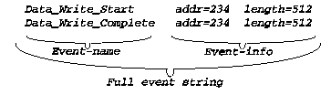
			Data_Write_Complete addr=234 length=512
			Data_Write_Complete addr=3879 length=32
are the same event type.
There is a graphical front-end for TimeLine, called TLPP-GUI.
To make a time-line:
After you have run a simulation model that produced an event-history file, or ran the SCHEDULER with the -hist option, do the following:- Invocation:
From the GUI or the graphical simulation control-panel, you can invoke the TimeLine
utility from the Tools menu, by selecting Tools / Post Analyze Event History.
TimeLine will prompt you for options from the text window.
Alternatively, you can invoke TimeLine from the command-line or from a script file by calling timeline with the name of your event history file, as in:
	timeline  EventHist.dat

Or, in the case of the SCHEDULER's history file:

	timeline  IdealEvHist.dat
- Selections:
2a. Event Selections:
TimeLine will scan the event history file and will list to the screen the types of events that were traced. It then asks you to select which type of event that you want to see the time-lines for by asking for the numbers or names of the relevant "on" and "off" events as listed.(The "on" event-name would be the "pen-down" event, and the "off" event would be the "pen-up" event (in the sense of a plotter). For instance, a processing time-line could use:
"on" = begin_process, "off" = completed_process.
For instantaneous events, the "on" and "off" event-names would be the same event, and this would draw a single point on the graph, instead of a line-segment.)2b. Annotations:
It will then ask what type of annotations you want to appear on the time-lines. Your answer will depend on how crowded your time-line is.For the time-line annotations, use: 0. No Annotations. 1. Event Number. 2. Event Name. 3. Event Info string. 4. Full event string. 5. Hyper-Notes.
Usually you would choose (3), but if the text is too crowded, you may try shorter versions (1-3), none (0), or hyper-notes (5). With hyper-notes, the annotations will not appear on the graph. The annotation for each a specific trace appears only when clicked.2c. Ranges of Time and Device Ordering:
TimeLine will ask several questions about the range of devices and time-range you want to have plotted. It will also ask about the sequence you want the devices listed on the vertical axis. You can specify a specific ordering.It will tell you the span of times that the events in the event file span. And it will ask over what range you would like output for. This allows you to focus on a sub-range.
Similarly, it will tell you the range of devices and allow you to select a subset if you would like. It also allows you to rearrange their order from top-to-bottom on the graph.
These features enable you to tailor the time-line graph to show just the resources you are interested in, in an order that is logical to you, and over specific time spans or interest.
In this way, TimeLine is helpful for data-reduction when analyzing the results from simulations of complex systems over long durations. Reducing the resultant plot-file size speeds-up the interactive response of the ultimate plotter/displayer, while saving file-space.
2d. Color Selections:
The TimeLine utility will then ask you what color you want each event to be, if you should want to colorize your graph.You may assign colors to specific event types. For each event-type you want colored, enter enough of the event string to uniquely identify that event-type, followed by the color.
Choose colors from: black, white, red, green, blue, cyan, violet, orange, yellow, pink, light-gray, dark-gray, and fuchsia.
	(example: suppose your timeline data file contains entries such as:

		    /brd3/dev8 @ 345.2: start modem9_3a
		    /brd3/dev8 @ 345.2: done modem9_3a

		Then a valid color entry for any 'modem' event could be:

		    modem blue

		Special thought should be given to your event-type naming
		convention so as to distinguish appropriate events.
	)
TimeLine will then produce a time-line plot file that shows the event history of devices versus time. The plot-file has a ".tln" suffix, such as:
"DTN.tln".
- Display the Graph:
Display the plot-file to the screen using XGRAPH:
xgraph DTN.tln
A graph window will then appear on your screen. XGRAPH contains several easy to use buttons on its panel for viewing or printing the graph. See XGRAPH for further information, such as producing hardcopy printout without running it interactively.
Hint: It is recommended that a command file be set-up with all
	the anticipated responses to the TimeLine program.
	To do this, you would run the TimeLine program only once
	interactively with the -capture option to capture your responses
	to a log-file, which becomes, in-effect, a command-file.
	Then run the TimeLine postprocessor from your command-file ever after.
	For example, run the TimeLine utility with input directed from that
	file, as in:

		timeline  events.dat  <  tline_log.com
Command-line Options
- -capture - To conveniently establish an editable command file for
driving TimeLine, the -capture option creates a log of your
interactive responses. Later, you can use the log file to drive the
TimeLine postprocessing automatically. This saves much tedious
interactive responses. It enables you to re-generate timeline graphs
quickly.
The log-file is called: tline_log.com
An example command file appears below. It appears as generated by the TimeLine tool. Note that your command files can contain helpful comments. You can conveniently edited it and re-apply it to TimeLine by directing the file as input.
	/************************************************/
	/* TimeLine PostProcessor Command File 		*/
	/*	(Item)			     (Response) */
	/************************************************/

	/* ------------------------- */
	/* Pen-down event name:      */		begin
	/* (I.E. Start of compute.)  */
	/* ------------------------- */

	/* ------------------------- */
	/* Pen-up event name: 	     */		end
	/* (I.E. End of task.)       */
	/* ------------------------- */

	/* ------------------------- */
	/* Annotation style:	     */		3
	/* ( 0. No Annotations.	     */
	/*   1. Event Number.	     */
	/*   2. Event Name.	     */
	/*   3. Event string.	     */
	/*   4. Full event string.   */
	/*   5. Hyper-notes. )       */
	/* ------------------------- */

	/* ------------------------- */
	/* Tick-marks (y,n) 	     */		y
	/* ------------------------- */


	/* ------------------------- */
	/* Device position list:     */
	/*	device  number	     */
	/*	device  number       */
	/*	...		     */
	/*	end		     */
	/* ------------------------- */
		end

	/* ------------------------- */
	/* Your devs ranged 1 - 456. */
	/*			     */
	/* Range of Devices To View. */		50	200
	/* (Min_device  Max_device)  */
	/* ------------------------- */

	/* ------------------------- */
	/* Time Range To View.	     */		2000.0	30000.0
	/* ( Min_Time  Max_Time )    */
	/* ------------------------- */


	/* ------------------------- */
	/* Event Color List:	     */
	/*   event_substring  color  */
	/*   event_substring  color  */
	/*	...		     */
	/*	end		     */
	/* ------------------------- */
		end
Note: Old versions of TimeLine used '-1' to end lists. Versions after 7-1-02 enable using end instead. - -thickness - This option enables changing the thickness of the activity
bars in the timeline graph. Line thickness is specified in points
(72-points to an inch, a standard of the printing world).
The nominal thickness value is 3.0-pts. If not specified by this option,
TimeLine attempts to adjust the thickness slightly when the number of
devices plotted is very few or very many, by making the thickness slightly
more or less, respectively as follows:
If ~2 devices, thickness=6.
If ~25 devices, thickness=3.
If ~200 devices, thickness=1.
- -v - Verbosity level. Example: timeline EvHist.dat -v 2.
This options enables additional
debugging printouts while the timeline tool processes data.
The -v must be followed by an integer indicating the level of
verbosity. The default level is 0, which is quiet. Currently, only
level 1 is defined, so any non-zero level is equivalent.
Other File Options
- TIME_BASE_UNIT - By default, the time-unit displayed to XGRAPH is set as 1.
You can change the time-unit by placing the keyword TIME_BASE_UNIT
(all caps) as the first line of your event-file, followed by the scale factor.
Example:
TIME_BASE_UNIT = 0.001 /* milli-Seconds. */ - Comm - Adding Communication Arrows.
This option enables display of communication events on the time-line graph. These are shown as diagonal lines running between devices, from the source device at the start of the transfer, to the destination device at the completion of the transfer. These become super-imposed on the process-timeline, and give additional insight as to the data movements, bottlenecks, and dependencies governing your system's execution. The arrows are sometimes called 'spider-webs', or 'spider-plots', due to their appearance.Format:
Comm src t1 dst t2 {color}Example:
Comm /board1/pe1 58.56 /board2/pe9 123.7 4Color must be a number (See colors) and is optional. The example above would appear as shown in figure 2 in green. (The processing events were added for context.)
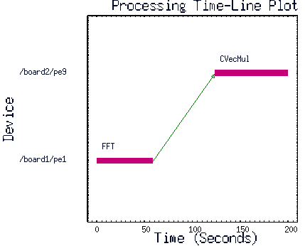
Figure 2 - Example communication arrow.